
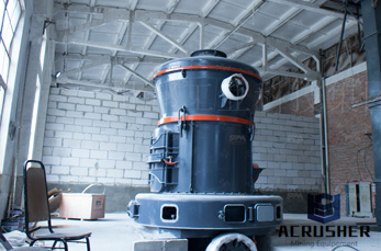
schematic figure of coal mill in a cement plant manufacturer Grasping strong production capability, advanced research strength and excellent service, Shanghai schematic figure of coal mill in a cement plant supplier create the value and bring values to all of customers.
 WhatsApp)
A simplified diagram of the pulverised coal plant is presented in Fig. 1.2. The illustration shows a simple schematic diagram for a typical pulverised coal combustion system. In this type of system, the coal is prepared by grinding to a very fine consistency for combustion. Typically, 70% of the coal is ground to pass through a 90 μm mesh screen.

A plant or a piece test. Whether you are looking for an entire cement plant or a single piece of equipment, we are the premium supplier. For new plants, we cover everything from evaluating initial quarry samples through to ongoing operation and maintenance services.
Cement manufacturing: components of a cement plant. This page and the linked pages below summarize the cement manufacturing process from the perspective of the individual components of a cement plant - the kiln, the cement mill etc.. For information on materials, including reactions in the kiln, see the ' Clinker ' pages.
vi Normalisation Methodology for Cement Sector 10.4 Coal Quality in CPP 43 10.5 Power Mix 44 10.6 Product Mix 48 10.6.1 Different cases in Cement Plants of Product Mix and use of Normalisation 52 10.7 Normalisation Others (REC Mechanism) 52 10.7.1 Environmental Concern 52
Figure 33. Simplified diagram showing the locations selected for the full-scale tests on the delivery of shingles into cement kiln. .....105 Figure 34: Flowchart summarizing various waste shingle delivery approaches tested: 1. Joint size reduction 2. Separate burner on top of main burner 3. Separate
Plants that burn waste fuels enjoy a negative fuel cost (they are paid by industries needing to dispose of materials that have energy content and can be safely disposed of in the cement kiln thanks to its high temperatures and longer retention times). As a result, the inefficiency of the wet process is an advantage—to the manufacturer.
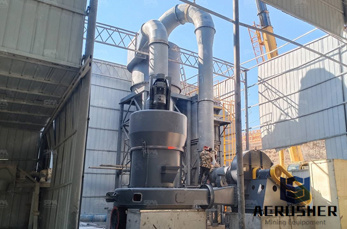
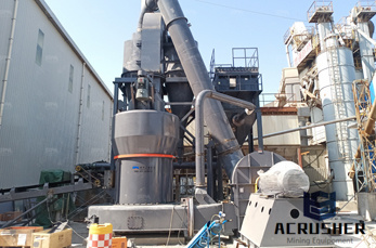
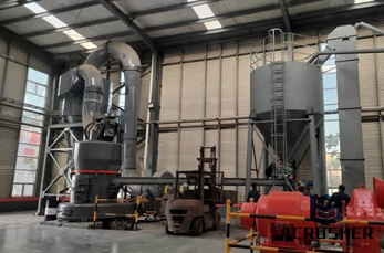
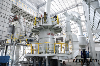
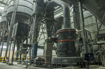
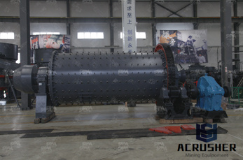
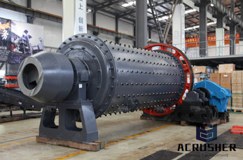
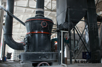
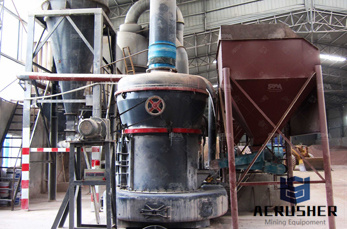
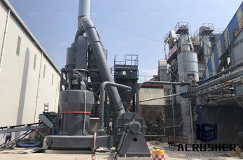
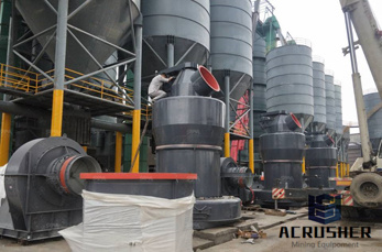
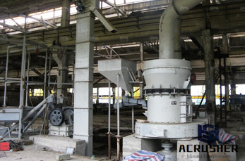
To support the production of cement, the plant has modern vertical roller grinding mills along with tube mills both for raw meal as well as coal. Cement grinding is achieved exclusively by tube mills/horizontal ball mills. The final products of the plant include PPC, OPC, PSG and other special cements.
Energy Efficiency Improvement and Cost Saving Opportunities for Cement Making An ENERGY STAR® Guide for Energy and Plant Managers August 2013 ENERGY STAR is a U.S. Environmental Protection Agency Program helping organizations and individuals fight climate change through superior energy efficiency. Document Number 430-R-13-009
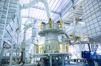
Figure 3 1 Simplified Process Schematic for Cement Making Crusher Limestone from ACCOUNTANC 13310456 at Columban College - Olongapo City
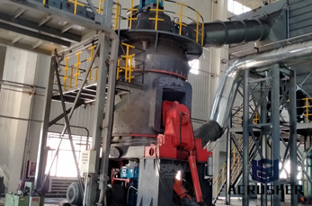
Figure 1 presents a diagram of the cement manufacturing process using a rotary kiln and cyclone preheater configuration. The schematic for a rotary kiln and precalciner configuration is very similar to that shown in Figure 1, with a calciner vessel located between the rotary kiln and cyclone preheater.
Aug 30, 2012· This saves the extra fuel cost and makes cement somehow economical. Raw materials are extracted from the quarry and by means of conveyor belt material is transported to the cement plant. There are also various other raw materials used for cement manufacturing. For example shale, fly ash, mill scale and bauxite.
Jun 17, 2013· POWER4Georgians! – Coal-Fired Power Plants Coal-fired power plants are a proven, reliable and efficient way to generate electricity, and are . Coal's value as a power plant fuel is greatly enhanced by its ability to supply power during .. Diagram of a typical coal .
materials are produced in portland cement manufacturing plants. A diagram of the process, which encompasses production of both portland and masonry cement, is shown in Figure 11.6-1. As shown in the figure, the process can be divided into the following primary components: raw materials
You may also find other latest coal mill,used in cement plant to dry and grind the coal in burning ... The coal mill we make is ... Get Price . function of coal mill used in cement plant. ... 1 Schematic of a Typical Cement Plant ... Cement Kiln Flue Gas Recovery Scrubber project, ... Get Price .
OFFICE OF AIR QUALITY PLANNING AND STANDARDS (OAQPS) FABRIC FILTER ... Monitoring system schematic 6 Figure 5. Installation location for a negative-pressure fabric filter application 11 Figure 6. Effects of sensitivity adjustment 11 ... Grinding mills Power plants Coal-fired boilers a Waste disposal Incinerators a
Impact Mills Grinding Action is carried out by aseries of hinged or fixed hammers revolving in an Improving Coal Pulverizer Performance and Reliability Coal Conveyer Coal Crusher Raw Coal Bunker To Boiler Furnace Raw Coal Feeder Exhauster Hot Air Motor Coal Pulverizer Figure 1: Simplified diagram detailing a direct-fired coal burning system.
ENERGY AUDIT OF THERMAL UTILITIES IN A CEMENT PLANT A. RAMESH 1, LEO. A. J2 & G. MADHU 3 1Division of Safety and Fire Engineering, School of Engineering, CUSAT Cochin, India 2Department of ...
Nov 17, 2012· coal mill/pulverizer in thermal power plants shivaji choudhury 2. 1.Introduction Coal continues to play a predominant role in the production of electricity in the world, A very large percentage of the total coal is burned in pulverized form. Pulverized coal achieved its first commercial success in the cement industry.
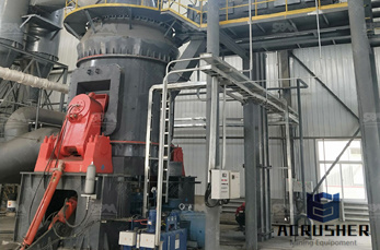
Next, in November 2014, Titan Cement ordered a Gebr. Pfeiffer SE type MPS 2800 BK vertical roller mill for coal grinding, to be set up at line 1 at its Beni Suef plant. In January 2015, Suez Cement, Italcementi's Egyptian arm, said that it would spend US$84m during the year to convert its Helwan and Tourah 2 cement plants to use coal.
Case Study of the California Cement Industry Fred Coito and Frank Powell, KEMA ... Labor is relatively small at a cement plant. Figure 1 shows historical consumption of energy by California cement plants. While coal is the primary ... A schematic of the cement production process is shown in Figure 3. The most common
In either scenario, EPA regulations will be more stringent with the elimination of wet ash handling and the phasing out of surface impoundments (ponds) for all coal-fired power plants.
materials are produced in portland cement manufacturing plants. A diagram of the process, which encompasses production of both portland and masonry cement, is shown in Figure 11.6-1. As shown in the figure, the process can be divided into the following primary components: raw materials
Section 6.01 Formula for target setting for Coal based Thermal Power Plant 5 (a) Design Net Heat Rate 5 ... Ex-Coal/Lignite/Oil/Gas based Thermal Power Plant Energy balance diagram 156 Figure 10: Ex-CCGT Energy balance diagram 157 ... Ex- GtG boundary and metering details for Agro based Pulp and Paper Mill 198 Figure 22: Ex- GtG boundary for ...

Note: Schematic and product recommendations are intended as a general guide only. Products listed are the product series names. Please refer to equipment builder manual for final lubrication recommendations or consult your Mobil™ Industrial Lubricants team for additional products.
WhatsApp)